DTPF Use Scenarios: SenseStream, ESMA, and SoDiBot
C. G. Prince
6 June 2005 (revised: 6/8/05; 6/10/05; 6/13/05; 6/14/05; 6/22/05; 6/24/05).
1. Introduction
We have now specified the requirements for the DataTime Processing Framework (DTPF; http://datatime.sourceforge.net/DevDoc/Requirements/Requirements.html ). As an initial step in evaluating those requirements, before we start designing the DTPF, we will outline use scenarios for DTPF.The primary use scenario is for the SenseStream application. In this document, we create a design for the SenseStream program ( http://www.cprince.com/PubRes/SenseStream ) in terms of the DTPF. We are designing the DTPF with the goals of flexibility of reuse of components, and modularization. In short, the framework as planned should enable us to create a version of SenseStream that is more easily modified and re-used than the previous (non-DTPF) version of SenseStream. Our goals in this Virtual SenseStream are to (a) layout a design for SenseStream in terms of DTPF, (b) to layout a series of hypothetical changes to SenseStream typical of those that have already been applied to SenseStream and, (c) attempt to evaluate if those changes to SenseStream would now be easier with it implemented in terms of DTPF. We also briefly present a Node architecture for the current ESMA (Epigenetic Sensory Model of Attention) model.
2. Description of Current Design of SenseStream
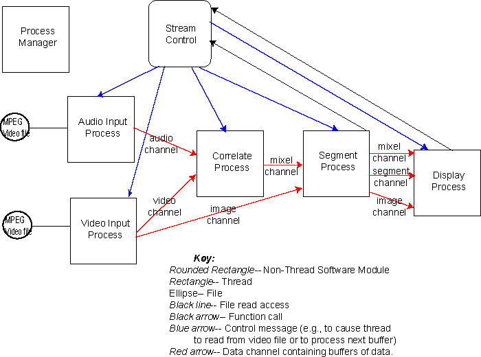
In order to design SenseStream in terms of DTPF, we need a description of its current design. The thread and communication organization of the program is given in this diagram:

Each data channel (BufferChannel type) is structured as a circular queue of fixed-length buffers. Each buffer is referred to by a frame number. Data messages are sent between processes that contain references to these buffers (i.e., frame numbers) within particular channels. The formats of the buffers referred to in these data messages, and sent between threads, are given by the following table:
| Data channel | Format of Buffer |
| Audio channel | Audio buffers have variable contents depending on what audio processing options have been selected using the SenseStream GUI. Audio processing options presently are: RMS, ZCR, Centroid, Rolloff, MFCC, and FFT (FFT is implicit in Centroid, Rolloff, and MFCC). For example, if RMS and ZCR processing are requested, then each audio buffer sent from the Audio Input Process to the Correlate Process using the audio channel will contain RMS and ZCR data. The Correlate Process is not knowledable about the specifics of the content of the buffers sent to it via the audio channel. Rather, it knows the length of the data, i.e., the number of audio features (n). The format of the audio features is floating point. Design note: What if there were two audio channels-- one for features represented as floating point, the other for features represented as integers? When the system starts, dependent on the features being used during that run, one or both of the audio channels could be utilized. |
| Video channel | The video channel contains processed visual features, as visual frames. Each visual feature is in floating point format. The particular visual feature that is used is selected via the SenseStream GUI. Visual features can be: PIC (Pixel Intensity Change), Y from YUV (grayscale), YUV, or RGB. The downstream process (i.e., the Correlate Process) knows that the visual features are represented as visual frames. The total length of the set of visual features (m) is used to determine the component size in these visual frames in the downstream process (i.e., the Correlate Process). Design note: As with the audio channel, what if there were two visual channels-- one for features represented as floating point, the other for features represented as integers? When the system starts, dependent on the features being used during that run, one or both of the video channels could be utilized. |
| Image channel | The first block of data in each of these buffers is the RGB format of the image, stored as a visual frame. The second block of data is the YUV format of the image, also stored as a visual frame. The downstream process Design note: It would appear to be a better structure to use two separate image channels-- one for RGB, the other for YUV. |
| Mixel channel | This channel contains buffers that are the mixelgrams. I.e., these are visual frames, with each component being a mixel, computed via the Hershey & Movellan (2000) algorithm. The format of the components are floating point values. The Segment Process also uses these buffers. A chunk of data immediately past the mixelgram in these buffers is used to store a thresholded version of the mixelgram, and a chunk of data past this thresholded version is used to store a smoothed version. |
| Segment channel | These buffers contain both a MutualInfoData data structure , and segmentation data (a vector of floating point values). |
Synchronization: Prior to the Correlate process, a particular frame number refers to buffers arising from the same temporal part each of the audio, video, and image channels. E.g., frame 20 refers to the visual frame, audio frame, arising at the same time (i.e., that are read correspondingly from the MPEG video file). Subsequent to the Correlate process (i.e., downstream of this process), each frame number refers to a mixelgram or other processed data (with the exception of the image channel, which maintains the frame number relation to the original data). The first S-1 frames output by the Correlator over the mixel channel will be all be filled with zeros, but on frame S and after, the frames represent mixelgrams of the current S buffers of audio and visual data. The segment channel is a processed version of the mixel channel, with the same frame numbers.
While SenseStream is running, control messages are sent to the Audio and Video Input Processes, telling them to get the next frame. Once the Audio and Video Input Processes have read from the MPEG file, these processes send messages to the Correlate Process telling it there are audio and video frames available. After the Correlate Process does its work, it sends a message to the Segment Process telling it there is a frame available. Similarly, the Segment Process, after it does its work, sends a message to the Display Process telling it there is a frame available. When the Display Process has completed its task on the frame, it calls a function on Stream Control to start the process again (i.e., a message to the Audio and Video Input Processes).
A description of the threads is given here:
| Thread | Responsibility |
| Process Manager | Creates other system threads (audio, video, correlate, segment, display), checks input files for validity, sets up buffer channels, calls setup methods on all of the threads, starts other system threads, stops processing. |
| Audio Input Process | Reads from MPEG video file; analyzes for audio features. |
| Video Input Process | Reads from MPEG video file; analyzes for visual features. |
| Correlator Process | Performs the Hershey & Movellan (2000) algorithm processing on the input audio and visual features, generating mixelgram output frames. Accepts changes in S parameter. |
| Display Process | Prepares images for display, does processing needed for changing display configuration (e.g., mask type), and carries out edge detection on mixelgrams (as a measure of the quantity of synchrony present in the mixelgram). |
| Segment Process | Segment Process thresholds mixels, and smooths mixels. Computes the centroid, and performs segmentation. Design note: Presently the Segment Process always thresholds the mixels, and smooths the mixels. It also always computes the centroid, and performs segmentation. However, the results of these operations are not always utilized. Presumably, this must reduce present run-time efficiency. |
3. Changes to SenseStream
We have applied various changes to SenseStream that might have been made easier if SenseStream was designed within the DTPF. These changes include:
Change Old SenseStream New (Planned) SenseStream (A) Adding in the MFCC audio feature 1. Changes to the Audio Input Process (AudioInputProcess.cpp) to compute MFCC's.
2. Changes to the GUI (AudioSetupPanel.cpp) to enable the user to select the MFCC option.
3. Changes to the Process Manager (ProcessManager.cpp) to add the MFCC's into the computation of the "n" parameter.
4. Changes to ProcessDefs.h-- change in enum for audio features.
Only an Audio Node should need to be changed. It will have a set of parameters. These parameters will be automatically presented to the user via the GUI. These parameters can be extended, as part of this change, to allow for the user selecting the MFCC option. The value of "n" will be computed by the Audio Node as a function of the parameters.
Optionally, an MFCC Node could be added downstream of the Audio Node. This new Node would have its own parameters (reflected on the GUI), and the value of "n" would have to be altered to reflect the use of the MFCC node, as would the data being passed on to the Correlate Process.
(B) Adding in the PIC visual feature 1. Changes to the Video Input Process (VideoInputProcess.cpp) to compute PIC.
2. Change to the GUI (VideoSetupPanel.cpp) to enable the user to select the PIC option.
3. Changes to the Process Manager (ProcessManager.cpp) to add the PIC's into the computation of the "m" parameter.
4. Change to ProcessDefs.h-- change in enum for visual features.
This change is similar to adding the MFCC audio feature, except it is in the visual processing stream. (C) Adding in Audio Attenuation 1. Change to Correlator.cpp to alter the mixel computation to using audio attenuation.
2. Change to CorrelateProcess.cpp -- to have the Correlator constructor now use the audio attenuation, and the alpha value, and to have the setup method use these too.
3. Change to the Process Manger to have it use the modified CorrelateProcess.cpp setup method.
4. Change to ProcessDefs.h-- add in field names for audio attenuation, and alpha.
5. Change to the CorrelateSetupPanel.cpp to add in audio attenuation and alpha.
Add a Node, downstream of the Correlator, with an input also from the Audio Nodes for RMS audio. (D) Adding in edge detection for quantifying mixelgrams 1. Changes to DisplayProcess.cpp to compute edge detection (Gaussian & Sobel filters on the basis of the mixelgrams) when required by GUI, and to code in the actual image filtering (PrepareFilteredImage).
2. Change to the GUI to enable the edge detection to be turned on. Changes made to: DisplayDefs.h, ImageDisplayBox.cpp
Add a Node between the Correlator and the Display to do filtering. (E) Connected region statistics, NND stats 1. Change to the GUI (CorrelateSetupPanel.cpp) to add in these as options.
2. Changes to SegmentProcess.cpp to compute these statistics.
3. Change to ProcessDefs.h
Similar to edge detection. (F) Total left/right luminance or PIC 1. Changes to VideoInputProcess.cpp (No changes made to GUI-- these changes were put in as conditional compilation.)
Probably best to implement as a new Node, downstream of the Video Node. Perhaps as a separate network of Nodes (a new "model") because this is separate from synchrony detection. (G) Saving data to files for FaceSynch testing 1. Changes put into CorrelateProcess.cpp. (No changes made to GUI-- these changes were put in as conditional compilation.) Implement as nodes downstream of the Video Nodes and Audio Nodes. The frames of audio and video data can be written on the basis of the frame numbers, which give access to the same temporal part of the video file. (H) Output mixelgrams as a video file. (Not implemented in SenseStream currently) Implement a new Video File Writer Node, taking audio and visual channels as input. (I) Only process rectangular subregions of the visual input or ignore rectangular subregions specified as a list of rectangular regions ((x1, y1), (x2, y2)). (Not implemented in SenseStream currently) If we put a constraint on processing only one rectangular subregion, then this becomes markedly simplified. This becomes a filter subsequent to the Video Input Node. This filter extracts out the rectangular subregion that will be processed, and passes that along dowstream. To process multiple rectangular subregions, this method could be applied separately, in serial (as opposed to in parallel) to each of the subregions. (J) Display a GUI representation of the audio waveform being processed (Not implemented in SenseStream currently) Implement a new Audio Display Node that takes audio input from one or more of the Audio Stream Nodes and graphically displays that data over time.
4. Re-Design of SenseStream in Terms of DTPF.
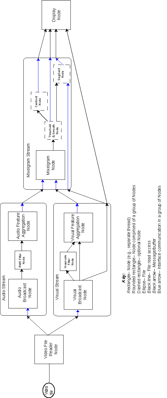
Given the above changes to SenseStream, and the DTPF, we plan to implement the overall SenseStream in the following manner.

Terminology:
Configuration parameters
Refers to parameters obtained from the end-user through the GUI.
Connections
Input/output interfaces for Nodes to other Nodes. Connections between nodes have particular data types. These data types specify the format of the data that this Node sends or expects to receive over a particular connection. These data types are used when configuring Nodes in order to determine which Node can be connected to which other nodes. The connection data types for a node can be obtained by querying that Node.
A description of the Nodes in the DTPF of SenseStream is given here:
| Node or Node Group | Responsibility |
| Video File Reader Node | Configuration parameters: Name of the video file to be processed Processing: Checks the video file to determine if it is of the correct format (e.g., does it have both audio and visual channels). Reads from audio & visual tracks of video file (e.g., using Mac OS Video API). For audio: Each downstream connected node receives buffers containing audio data frames-- these are arrays of raw audio, containing data sampled at the same time as a visual frame. Buffer numbers sent from this Node correspond to visual frame numbers. For visual: Each downstream connected node receives buffers containing visual data frames-- these are arrays of visual data, in the format as given by the configuration parameter, corresponding to a visual frame. Buffer numbers sent from this Node correspond to visual frame numbers. Connections: An audio channel to the audio stream, and a visual channel to the visual stream. |
| Audio Stream | Configuration parameters: None. |
| Audio Broadcast Node | Configuration parameters: None. Processing: Copy input to broadcast output channel. Connections: Input: channel containing the raw audio data. Output: Broadcast buffer channel. |
| RMS Filter Node | Configuration parameters: None. Processing: Analyzes raw audio for RMS (root-mean sequared) audio features. Connections: Input: Buffers containing frames of audio data. Output: Buffers containing audio features processed from the input audio frames. The frame number correspondence to the visual frames is maintained. That is, for each audio frame obtained on the input, a single filtered audio frame is sent to the output. |
| Audio Feature Aggregation Node | Configuration parameters: None. Processing: Accepts buffers containing audio features. Aggregates them into a single output buffer, and sends them downstream, along with a number indicating the number of scalar elements in the resulting output buffer. Connections: Input: Buffers containing audio features. Output: Buffers containing aggregated audio features. |
| Visual Stream | Configuration parameters: scale at which to process visual frames, and the visual features which are to be used (e.g., grayscale, or RGB visual features). |
| Visual Broadcast Node | Configuration parameters: None. Processing: Copy input to broadcast output channel. Connections: Input: channel containing the raw visual data. Output: Broadcast buffer channel. |
| Grayscale filter Node | Configuration parameters: None. Processing: Analyzes RGB visual for grayscale (intensity) feature. Connections: Input: Buffers containing frames of visual data. Output: Buffers containing grayscale features processed from the input visual frames. |
| Visual Feature Aggregation Node | Configuration parameters: None. Processing: Accepts buffers containing visual features. Aggregates them into a single output buffer, and sends them downstream, along with a number indicating the number of scalar elements per pixel in the resulting output buffer. Connections: Input: Buffers containing visual features, on a frame basis. Output: Buffers containing aggregated visual features, on a frame basis. |
| Mixelgram stream | Configuration parameters: Flags indicating whether segmentation, thresholding & smoothing, and centroid computations are to be carried out. |
| Mixelgram Node | Configuration parameters: S, the processing window size. Processing: Performs the Hershey & Movellan (2000) algorithm processing on the input audio and visual features, generating mixelgram output frames. Connections: Input: (1) Buffers containing aggregated audio features. (2) Buffers containing aggregated visual features. Output: Buffers containing mixelgrams. |
| Segment Node | Processing: Optionally performs segmentation. Connections: Input: (1) Buffers containing mixelgrams. (2) Buffers containing visual images. Output: Visual images segmented by color, on the basis of the mixelgrams. |
| Threshold & Smooth Node | Processing: Optionally performs thresholding and smoothing. Connections: Input: Mixelgram buffers, Output: Thresholded & Smoothed Mixelgram buffers. |
| Centroid Node | Processing: Optionally computes the centroid of the current data frames. Connections: Input: Buffers containing mixelgrams. Output: (x, y) coordinates of center of mass of mixelgrams. One coordinate pair per mixelgram. |
| Display Node | Configuration parameters: Which of the input data are to be visually displayed-- i.e., which of the images, mixelgrams, smoothed & thresholded mixelgrams, centroid coordinates. Processing: Displays input data. Connections: Input: Buffers containing (1) mixelgrams, (2) thresholded & smoothed mixelgrams, (3) centroid coordinates, and (4) images. |
5. Other Uses of DTPF
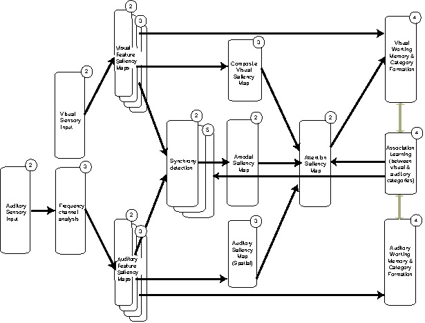
The following is an architecture we have proposed (but not yet implemented) for modeling word-object mapping in infants. Round cornered rectangles represent model processing components. Arrows represent data communication between model components. Circled numbers in the upper right of the rectangles indicate a plan for sequence of implementation. (There is no number "1" because the modeling framework itself is the first step towards such a model).

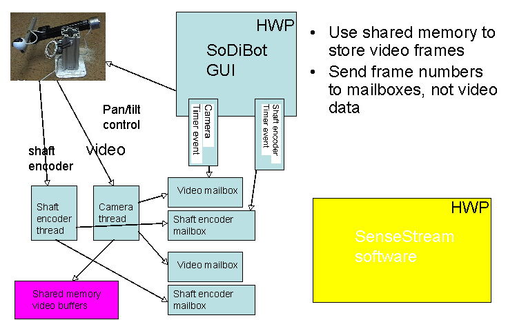
The following is an initial description of an architecture we have partly implemented for connecting the SoDiBot robot to SenseStream for performing self-other discrimination.

6. Conclusion
In the above table of changes to the old SenseStream, and the changes as we plan them for the new SenseStream, the main impacts of changing to a DTPF SenseStream will be the following. First, changes should be isolated to smaller parts (e.g., fewer files) of the code by the use of configuration parameters. No longer should a change to the processing need to explicitly add parts to the GUI to obtain new parameters from the user. Parameters will be requested by the Nodes, and these requests will be automatically formed into a GUI interface. The parameter request code for the Node will be contained in the same file(s) as the processing code for the Node. Additionally, as part of the DTPF functionality, we will be enabling easy creation and introduction of new Nodes, along with its channel/data interface to other Nodes. It should be relatively easy to create a new node, and the communication structure to other Nodes should be straight forward. This should also facilitate the re-use of Nodes in other networks of nodes (e.g., other models).